

So I’m a big fan of Raspberry Pi and I’m also a fan of Xilinx’s Zynq chipset, then I discovered that a German based company called Trenz Electronic had made a dev board that blended the two together. Of course had to get my hands on it and I ordered it straight from Trenz’s website. Since then, Digikey has picked then up for distribution, so if you’re interested you can pick your own up here (if you live in the US like I do, ordering from Digikey is a bit easier compared to directly off Trenz’s website). The Zynqberry is a Zynq-based FPGA development board with the form factor and peripherals of the Raspberry Pi 2 Model B including: 10/100Mb Ethernet, 4 USB 2.0 ports, 512 MB DDR3L SDRAM (REV3), 16 MB flash memory, HDMI, DSI, 3.5mm stereo audio, CSI-2, and micro-USB for UART, JTAG, & power.
With the power to re-create a lot of my favorite Pi projects with the added power/capability of the Zynq FPGA, I was itching to get a good base project setup to use as a starting template. First things first, it’s import to note that this tutorial is based on Vivado 2018.2, which means programming any Zynq-based chip requires a first-stage boot-loader. So if you’re using any version of Vivado prior to 2017.3, this tutorial may not work exactly for you (in theory though, I can’t think of why it wouldn’t).
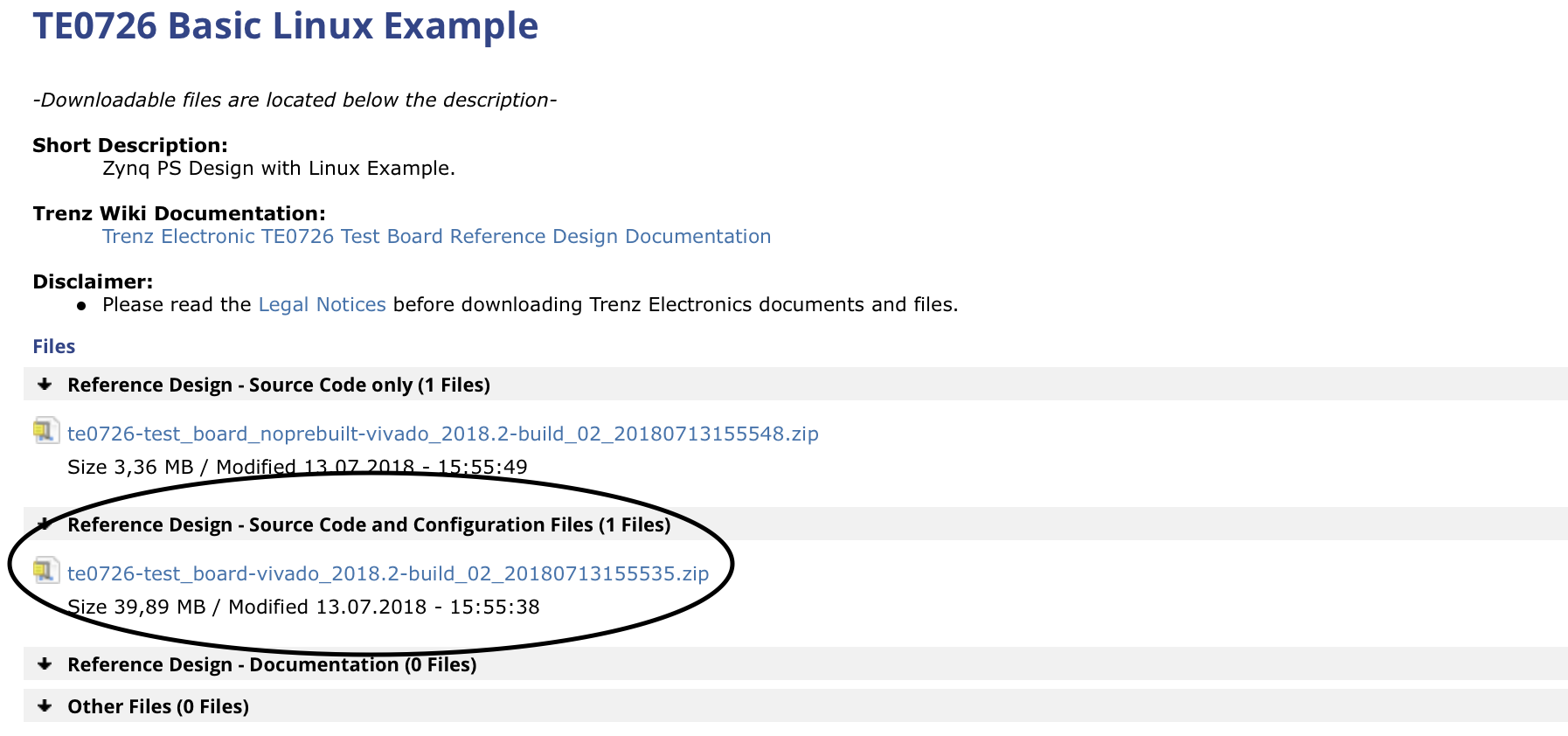
Anyways, with that disclaimer out of the way, my first step I always take with a new FPGA dev board in Vivado is to find & install the board preset/part files. I headed over to the Trenz Electronic wiki page where they have a ton of great resources and documentation of all their products. I did have to do a bit of digging, but I eventually found the board part files were included in one of their pre-built image projects. You’ll see two zipped up projects here, the second one has all of the pre-built images for the Zynqberry that Trenz intends for use to verify the hardware functionality and is the one that I pulled the board part files from to install into Vivado.
The board files are located under ./test_board/board_files/TE0726
To install into Vivado, copy the entire folder TE0726 itself and paste it into the following Vivado directory:
./opt/Xilinx/Vivado/2018.2/data/boards/board_files
If Vivado is running already, close and relaunch it to give it a chance to re-index this directory properly.

I have the REV3 512MB model (TE0726-03M part number), the TE0726 folder contains the board files for this particular board.
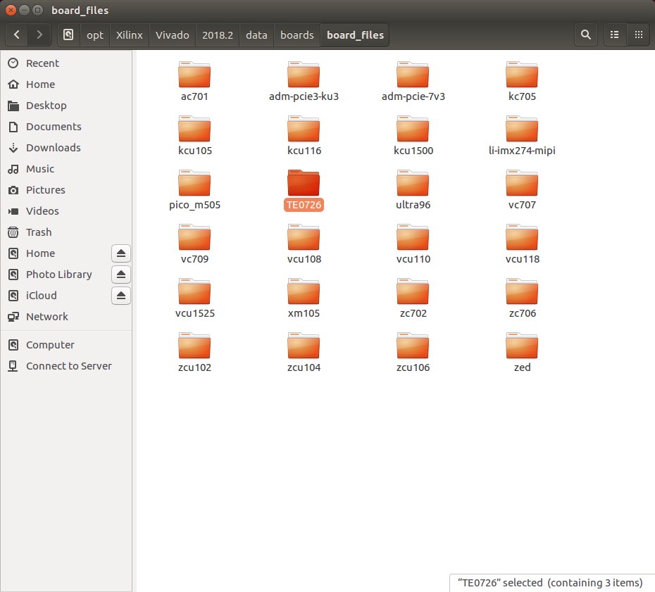
I copy+pasted this folder into Vivado’s directory (which I actually did via command line).
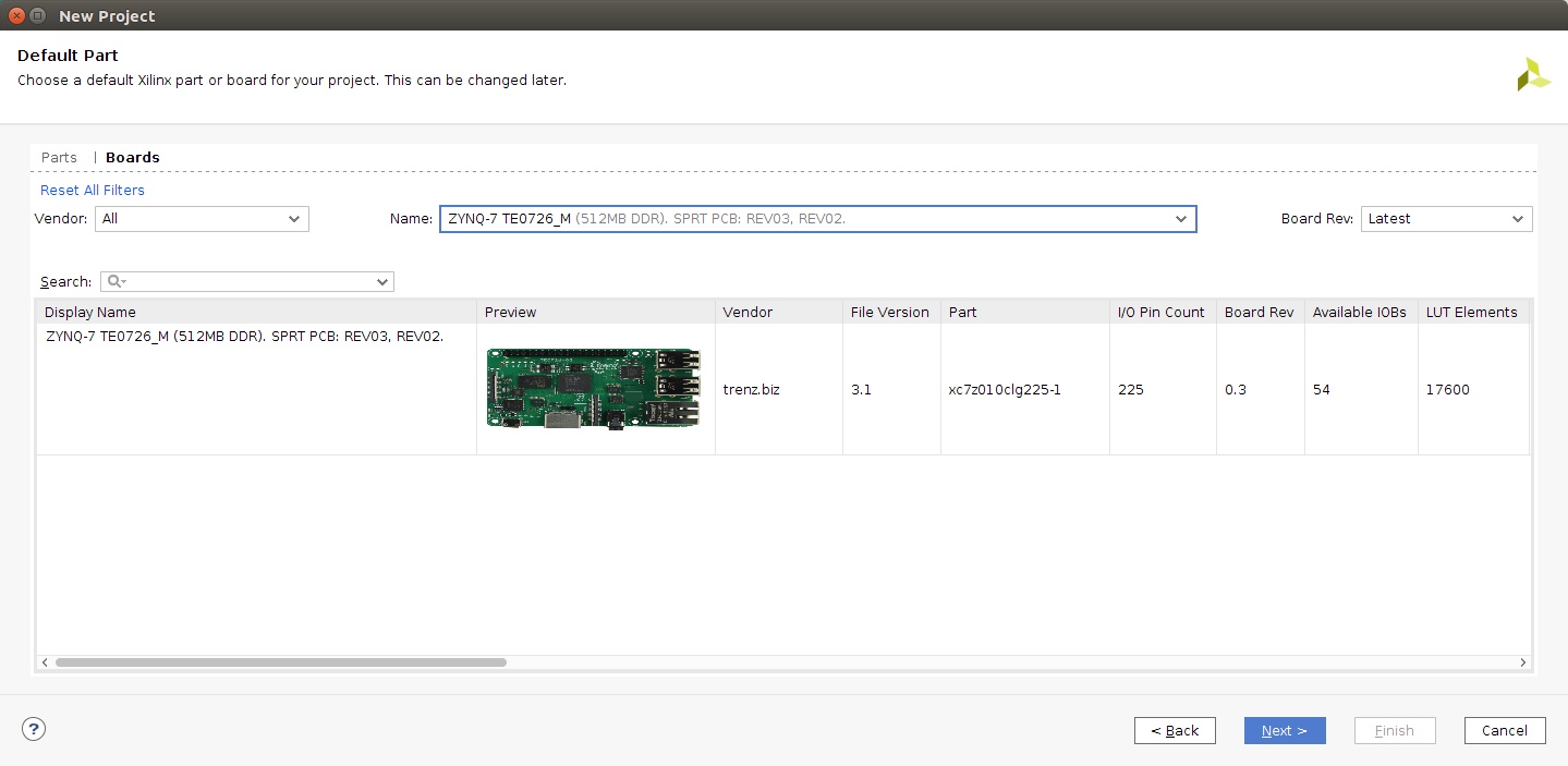
Upon Vivado’s relaunch, I selected to create a new project using the Zynqberry as my default part.
The first step in pretty much any new Vivado project is to create a block design. The block design in Vivado is where you instantiate your soft processors like the MicroBlaze and/or the interface to the ARM processors and other peripherals in the Zynq chip. For this project, since I wanted it as my starting template for any project I use the Zynqberry for, I just wanted the absolute bare bones. This involved just adding the Zynq IP block to my block design and applying the Zynqberry presets by running block automation.


The one thing that block automation and connection automation won’t do is connect the system clock out for the fabric (FCLK_CLK0) to the master AXI general purpose interface of the Zynq system (M_AXI_GP0_ACLK) as shown in screenshot above, and you will get an error if you try to validate your design without connecting theses ports. AXI is Xilinx’s proprietary interface it implements in the block design to allow for IP blocks to communicate, and it needs a source clock for that communication.
Once everything is connected and ready to go in the block design, run validation:

The Run Validation button in the tool bar of the Block Design.
After I successfully validate my block design, the next item on my list for my workflow in Vivado is to create an HDL wrapper for the block design. This top level wrapper instantiates the block design and is where you instantiate your custom HDL code if you have any. In the design sources tab, you’ll only see the block design (.bd) file at first, which I have circled in the screenshot below. To create the HDL wrapper, right click on the block design file in the design sources tab, select the “Create HDL Wrapper…” option, then select the option for Vivado to manage the file and auto-update it, and click ok.

What the design sources tab will look like after creating the top level HDL wrapper for the design.
At this point, the barebones are together in Vivado and ready to be compiled. The first step is to run Synthesis (F11). When Synthesis is complete, Vivado will prompt you to run Implementation next, and after you run Implementation is complete, Vivado will then prompt you to generate a bitstream. Once this bitstream is generated, it needs to be exported to the workspace SDK will use for any of your embedded applications to reference. Under the File tab, select ‘Export Hardware’, check the box to ‘Include bitstream’, and leave the ‘Export To:’ field as “<Local to Project>”.

After exporting the hardware and bitstream to the SDK workspace, launch SDK by again going to File and select ‘Launch SDK’. Leave both the ‘Exported location:’ and ‘Workspace’ fields as “<Local to Project>”. In my personal experience, I’ve found that it’s so much easier to leave everything in the default locations of where Vivado wants to place files because there are so many buried pointers you have to change manually that are too easy to miss/forget if you want to place any files in a different location.

Upon launch, SDK will only contain a hardware platform (which is what you just exported from Vivado). Overall, three different applications need to be created: the hello world application, the first stage bootloader for booting up from the QSPI flash, and a first stage bootloader for the initial flash of the Zynqberry to tell it to boot from JTAG initially. It doesn’t matter which order you create the application projects in, but I like to start with the main application which is the Hello World application in this case, then I created the FBSL for booting from flash memory, and the third application I created was the special FBSL to initially boot the Zynq ARM processor from JTAG to program the flash memory. Each new application project is created the same way by going to File > New > Application Project and the following window comes up:

First, the application needs a name; and again, I highly recommend leaving the ‘Use default location’ option checked.
Since all of these applications are bare metal applications, the OS platform will remain standalone on all three you create.
The hardware platform will already be autofilled with the one exported from Vivado.
There will be two processors available under the Processor tab, which are the two ARM processors within the Zynq chip. Since they are exactly the same, it really doesn’t make any different which one you use so I just left it on the one it defaulted to, but since we have to make three separate applications just make sure you select the same processor for each one.
I personally prefer to write my applications in C versus C++.
Finally, each of these applications need their own Board Support Package (BSP), so select the ‘Create New’ option if it’s not already selected. The name will automatically be filled in with the same name as you typed into the Project Name field with ‘_bsp’ appended to it. I like to use this default naming convention, but it’s another personal preference of mine.
Once making all of these selections, click the ‘Next>’ button to specify the application type.
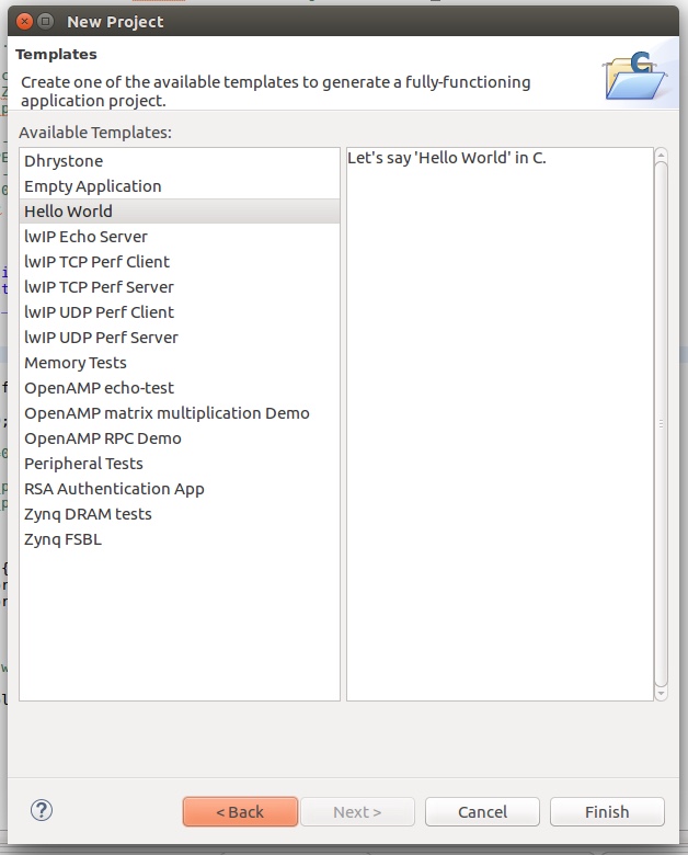
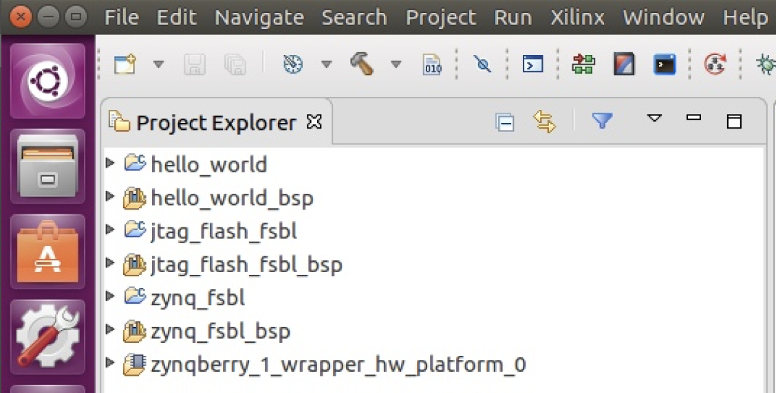
For the Hello World application, select the Hello World template, and for the two first stage bootloader projects select the Zynq FSBL template. Once you have all three applications created, your Project Explorer pane in SDK should look something like this:
The FBSL application for the Zynqberry to boot from its on-board QSPI flash memory (this is the FSBL that is called every time the Zynq is power cycled after it has been programmed) can be left as-is and doesn’t need any custom edits (it’s the one I have titled “zynq_fsbl” in the above screenshot). The other FSBL application does however need a couple of minor edits. This is the FSBL that is only used once while programming the Zynqberry’s on-board QSPI flash memory (it’s the one I have titled “jtag_flash_fsbl” in the above screenshot). This special FSBL doesn’t need to index the DDR memory and it also needs to tell the Zynq ARM processor to boot from JTAG. So comment out the code for indexing the DDR, and change the boot mode to JTAG. You’ll also need to reset the DDR’s memory address to zero, which SDK will throw a warning about but it can be safely ignored for now.

Comment out lines 312 - 322 for the DDR read/write test, and reset the base address for the DDR to zero as shown on line 305. The banner edits on lines 300 - 303 are optional, but I recommend for debugging.

Add the code shown on line 395 to specify the boot mode as JTAG.
These next edits to the Hello World application are definitely optional, but I do recommend because by default the application only prints out “Hello World” once at power up and doesn’t give you a chance to get the SDK serial terminal connected to be able to catch it. I recommend changing it to either print in an infinite loop (lines 66 - 70 in the screenshot below) or a large number of times (commented out in lines 59 - 64).
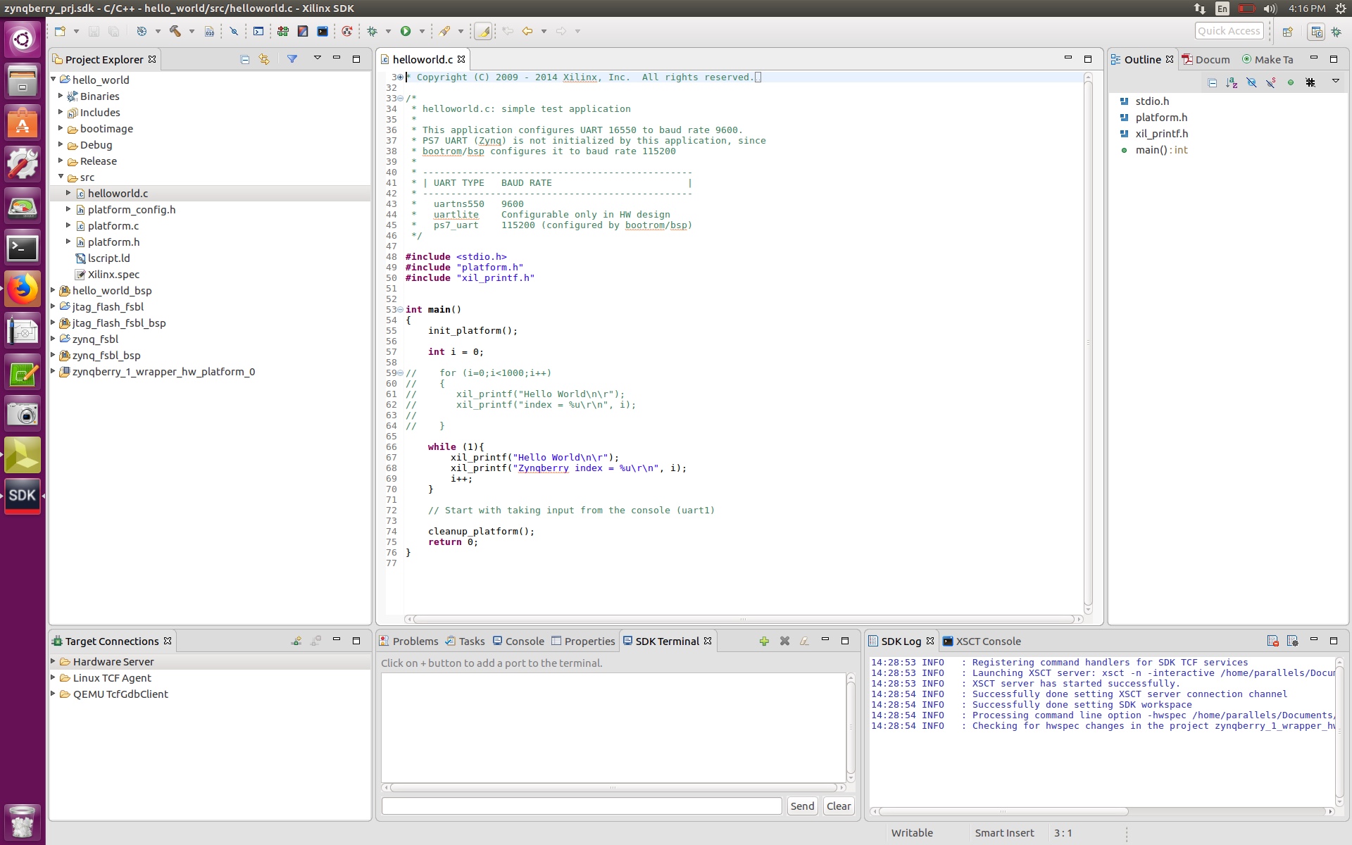
Ignore the comment on line 72, that’s just a preview of the next blog post….
Now that all three applications are ready to go, the next step is to create a boot image. Right click on the application folder for your hello world application and select the ‘Create Boot Image’ option.

The application folder of my Hello World application in Project Explorer.

Select the ‘Create new BIF file’ option, and Zynq for the Architecture. There are three partitions that need to be preset in the boot image: the bootloader (which is the .elf file from the FBSL application for the Zynqberry to boot from its on-board QSPI flash memory), the bitstream exported from Vivado, and the .elf file from the Hello World application. Since the application is being programmed into the on-board flash memory of the Zynqberry and not being placed on an SD card, the output file type needs to be .MCS not .BIN since the .MCS file type contains more programming information along with the data from the .elf files and bitstream partitions compared to the .BIN file type that is solely the binary data of the .elf files and bitstream partitions. Once all these selections are made, click ‘Create Image’.
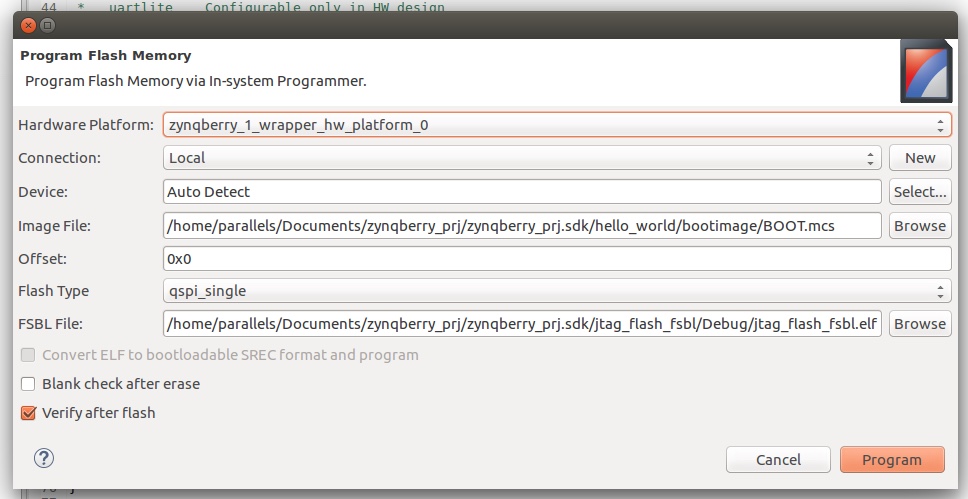
Now it’s finally time to program the flash of the Zynqberry! Click the Program Flash button in the toolbar and fill in the following fields:
Hardware Platform: the one exported from Vivado (auto-filled).
Connection: Local
Device: Auto Detect
Image File: Use the file path specified under Output path of the .MCS file when you created the boot image.
Offset: 0x00
Flash Type: QSPI single
FSBL type: file path to the .elf file of the special FBSL to initially boot the Zynq ARM processor from JTAG
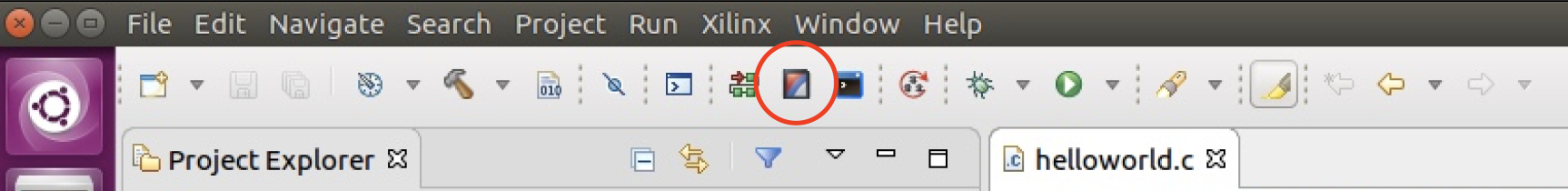
Program Flash button in SDK tool bar.
Click ‘Program’ and watch the embedded magic start to happen!

After successfully programming the Zynqberry, disconnect and reconnect micro-USB cable and navigate to the SDK Terminal tab in the bottom center window of SDK. Click the ‘+’ button to add the new serial connection. Select the USB port the Zynqberry appears as on your computer and set the baud rate to 11520 (which is the Zynq standard).


My Zynqberry showed up as ttyUSB1.
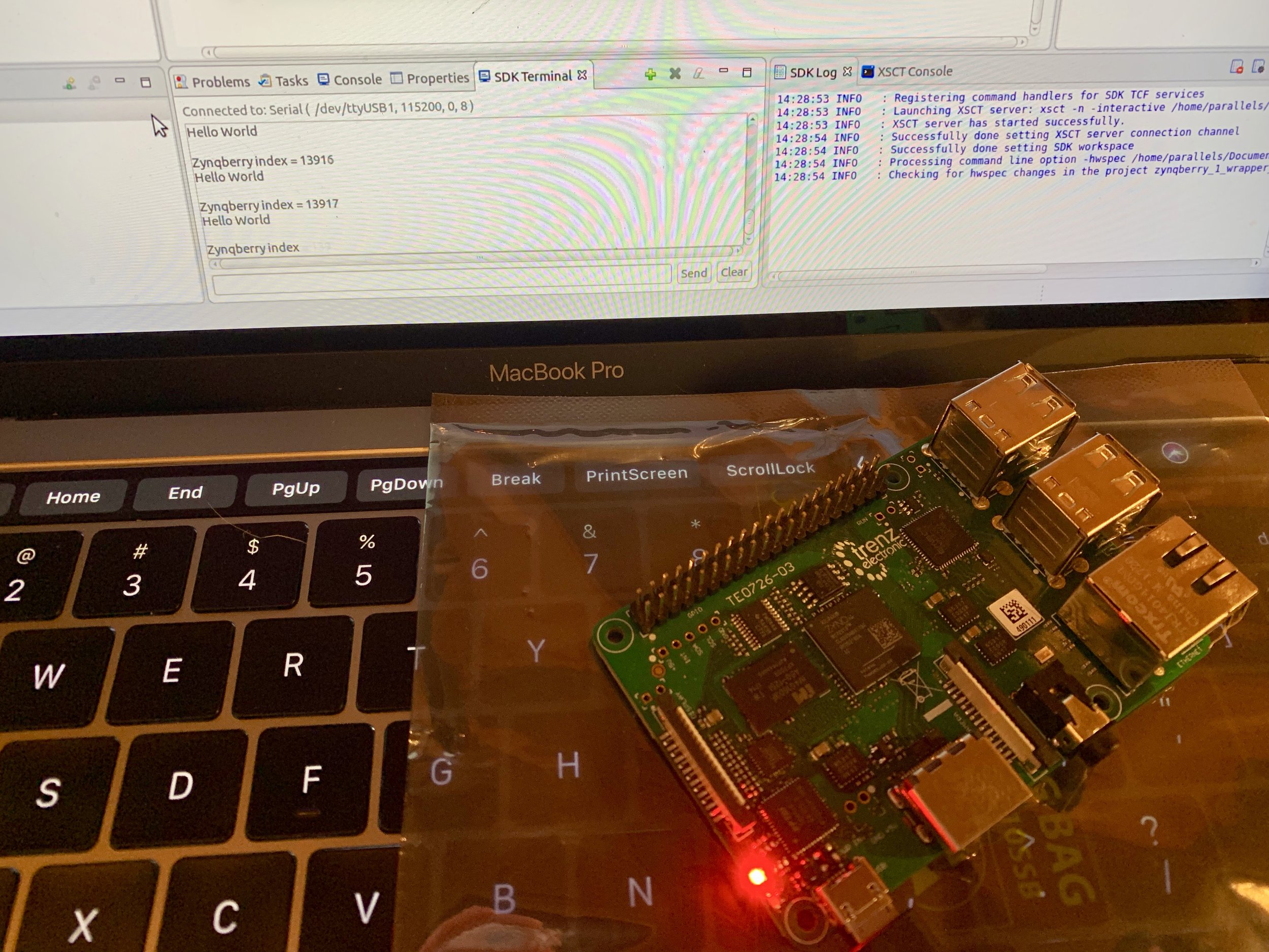
Woohoo! The Zynqberry is up and running like a champ! I hope you enjoyed this blog, I’m super excited to see what this little board can do and how it’s going to chalk up against the fan favorite Raspberry Pi. Stay tuned for more!